This issue's content:
Create a new PCB project
Create a new electrical schematic diagram
Add circuit schematics to the project
Create a new PCB project
In Altium Designer, a project includes all file associations and design related settings. A project file, such as xxx. PrjPCB, is an ASCII text file that includes files within the project and related output settings, such as print settings and CAM settings. Files unrelated to the project are called 'free files'. The files associated with the schematic and target output are added to the project, such as PCB, FPGA, embedded (VHDL), and libraries. When the project is compiled, design validation, simulation synchronization, and comparison will all be carried out together. Any changes to the original schematic or PCB will be updated during compilation.
The creation process for all types of projects is the same. This chapter introduces the process of creating a PCB project as an example. First, create a project file, then create a new schematic and add it to the newly created project. Finally, create a new PCB and add it to the project like a schematic.
As the beginning of this chapter, let's first create a PCB project:

图 6-1 PCB 工程的创建
Select File>>New>>Project>>PCB Project, or click Blank Project in the New option of the Files panel. If this option is not displayed on the interface, select Files from System. You can also select Printed Circuit Board Design in the Pick a Task section of the Home Page in Altium Designer software and click on New Blank PCB Project.
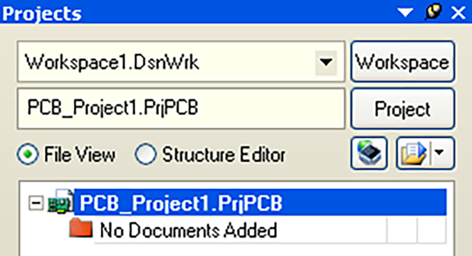
Display the Projects panel box on the screen. The new project file PCB-PProject1.PrjPCB has been listed in the box without any files, as shown in Figure 6-1.
Rename the project file (with extension. PrjPCB), select File>>Save Project As. Save to the location you want to store, enter the project name MultivibratorPrjPCB in File Name and click Save to save.
Next, we will create a schematic file and add it to the empty project. This schematic is an example of a non-stationary multi harmonic oscillator in the tutorial.
Create a new electrical schematic diagram
Create a new circuit schematic by following these steps:
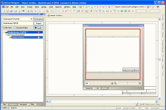
Select File>>New>>Schematic, or click on Schematic Sheet in the New option of the Files panel. A blank circuit schematic named Sheet1.SchDoc will appear in the design window and will be automatically added to the project. The circuit schematic will be located in the Source Documents directory of the project.
By selecting File>>Save As, you can rename the newly created circuit schematic. You can navigate to the desired hard drive location by entering the file name MultivibratorSchDoc and clicking Save.
When the user opens the blank circuit schematic, they will find that the engineering directory has changed. The main toolbar includes a series of new buttons, including a new toolbar, a menu toolbar for creating new items, and a chart layer panel. Users can now edit circuit schematics.
Users can customize the appearance of many projects. For example, users can reposition the panel or customize menu options and toolbar commands.
Now we can add this blank schematic to the project before continuing with the design input, as shown in Figure 6-2.

图 6-2 新建电路原理图
Add circuit schematic to the project
If the circuit schematic added to the project is opened as an empty document, you can right-click on the project file name and select the Add Existing to Project option in the project panel, select the empty document, and click Open. A simpler method is to simply drag and drop with the mouse in the Projects panel
Pull the blank document to the panel in the engineering document list. The circuit schematic is in the Source Documents project directory and has been connected to the project.